The demand for construction continues to grow year after year, putting more pressure on the global value chain. Construction labor shortages worldwide, even across OEMs and Integrators that supply construction, makes us question if modular and off-site construction are really solving the manpower issue or just moving it somewhere else. Compounding this situation, and knowingly or unknowingly, the ongoing advocacy of project and construction management practices has pushed project practitioners, as well as many educational institutions, to maintain a strong focus on project administration (e.g., submittals, request for information, progress reporting and forecasting, etc.), creating a significant gap in how even experienced project teams engineer their production processes and operations. In some instances, the situation has become so dire that people responsible for construction do not have experience or knowledge in actual construction work. The gap and confusion across the global engineering and construction industry is such that many operate under the belief that because they have a schedule (gantt-chart based flow), project production is already engineered.
A question the industry should explore the answer to is how to significantly increase the throughput of our project production systems using an optimal number of resources, and in so doing, contribute to addressing labor shortages doing more with less. This paper provides a framework for the application of Computer-Aided Production Engineering (CAPE) as a methodology to enable capital project teams to systematically define, engineer, test, and standardize production processes and operations (repetitive or not) looking at concurrent product and process design and using a science-based approach. The paper illustrates the benefits CAPE can deliver to the industry and how to make it work through two real-project examples.
Keywords: Computer-Aided Production Engineering, Operations, Operations Science, Production, Production Engineering, Production Systems, Standard Processes.

Roberto Arbulu is Senior Vice President of Technical Services for Strategic Project Solutions. He has more than twenty years of experience in the delivery and optimization of energy, industrial, technology, and infrastructure capital projects and has worked with numerous owner operators and service providers across North America, South America, Europ ...

Lon joined SPS|Technical Services in 2009. Since joining SPS|Technical Services, he has worked on projects for a provider of electric vehicle charging infrastructure and services in Israel and Denmark, the construction and commissioning of facilities to support onshore field development in Bakersfield, California, and the Chevron-led Chuandongbei Gas ...
The demand for construction continues to grow year after year putting more pressure in the overall value chain including supply systems for materials and permanent equipment (OEMs), as well as access to manpower, construction equipment and all construction-related services. In the United States alone, the Associated Builders and Contractors (ABC) organization (with 23,000 member companies) predicts that about a million new workers will need to join the trades in the next two years to meet demand (439,000 and 499,000 in 2025 and 2026 respectively) [1].
In the United Kingdom, something similar is happening at a lower scale. The Construction Industry Training Board (CITB) indicates that the overall number of extra workers needed for the 2025–2029 period is estimated at 47,860 per year, which means the UK construction industry needs to recruit the equivalent of 239,300 extra workers over the next five years [2]. Europe is struggling too. For instance, the European Centre for the Development of Vocational Training (CEDEFOP) expects that until 2035, an estimated 4.2 million job openings will need to be filled [3]. On the other hand, OEM Equipment Providers and Integrators are also struggling to find the workforce they need. For instance, the Manufacturing Institute in the U.S. has estimated that in average there are more than 800,000 open jobs a month in that sector alone [4].
Based on the above facts and predictions, if the global construction industry believes that moving work offsite to be performed by OEMs and Integrators, including the significant engineering efforts required to modularize the asset, is part of a solution to the shortage of construction manpower, we may need to re-think that strategy as this problem is across the value chain. Arguments will be made that allocating part of the work to the OEMs and Integrators will reduce overall project lead time. That may be the case, but by how much? Certainly not enough to cover a significant amount of the gap. Moving the problem from one place to another, upstream in the value chain, is not going to assist the industry to meet the accelerated demand for construction. But this is a complex problem to solve with multiple dimensions touching several industries, so the question is what can the construction industry do about it other than recruiting and training more workforce? It is not the intent of this paper to research the multiple possible answers to this question, but rather to propose that one of the strategies the industry should explore is how to significantly increase the throughput of project production systems using an optimal number of resources (e.g., labor, equipment), and in so doing, contributing to address the labor problem.
To operationalize methods to answer this question and make it a reality, the construction industry must switch to a robust production mindset. Unfortunately, the advocacy of project and construction management practices has pushed project practitioners, as well as many educational institutions, to maintain a strong focus on what today is known as project administration. In fact, these practices channel efforts to work on processes such as preparation of submittals, requests for information, development and maintenance of schedules at multiple levels, capturing and reporting project progress as well as computing the progress to date to generate a forecast of project completion, plus the adoption of technologies, including robots, that enable all this.
The above-mentioned practices, coupled with fragmentation in the industry, are forcing many to be removed from the work (project production), creating a significant gap in how even experienced, multi-company project teams, engineer their project production processes and operations, if they even do it systematically. Furthermore, the belief that the combined years of experience of a project team leads to optimal outcomes is questionable, otherwise, we should see more often a correlation between seasoned project teams and better performance including more evidence of project success, which based on the abundant cases of less-than-optimal project performance, we don't always see.
Although this paper does not question the need for project administration, it does propose that more or better project administration and construction management is not the solution to ensure the desired project performance is effectively achieved, nor to get even close to effectively answer the question posted above and address the labor shortage problem.
In addition to a strong focus on production systems as the answer to how to increase throughput without investing in unnecessary resources and associated cost and use of cash, this paper proposes the need to augment current project delivery practices with CAPE, a robust methodology to engineer project operations – repetitive or not – such as fabrication, assembly, testing, transportation, installation, commissioning and decommissioning as well as maintenance of operating assets. In so doing, enable reduction of cycle times, establish the type of resources to do the work and how to better utilize them, put in place a robust method to standardize production operations, while enabling a project-administration driven industry to get much closer to the work to design and optimize it.
The terms Production Engineering and Computer-Aided Production Engineering are not new in the world of production systems. Originally created in the manufacturing industry, Production Engineering emerged as a new field of Engineering, which over time ended up being performed concurrently with Product Development. Like applying other fields of engineering such as mechanical and electrical, Production Engineering brought the ‘how to’ dimension including, but not limited to, determining the feasibility of physically making a product within certain constraints (e.g., time, cost, volumes, available production technologies, etc.), how to do it effectively (e.g., process, systems, workcell design, tools, etc.), while informing the final development of the product. In other words, concurrent product and production process design. With the development of digital prototyping technologies, which started in the 1950s, practices such as Computer-Aided Design (CAD) and Computer-Aided Manufacturing (CAM) emerged, as so Computer-Aided Production Engineering, forming what many know in the manufacturing industry as Computer Integrated Manufacturing (CIM). Often in Manufacturing, when designing processes to satisfy the requirements of the design of the product, it is an iterative venture with many controlled tests of design elements sometimes resulting in minor or even major redesign.
As Novak-Marcincin & Kuzmiakova (2009) [5] indicate, “CAPE started as an off-line programming tool for automated manufacturing equipment…Soon the advantages of using CAPE tools upstream became clear. It was necessary not to use CAPE only for programming equipment, but also use it up-front, for designing the whole workcell. Enhanced CAPE tools enabled manufacturing engineers to design the complete workcell in a faster, optimized and error-free fashion. The ability to view the equipment working in a manufacturing environment allowed for much tighter designs with less error margins, as well as more accurate time and flow calculations. Thus, CAPE took a significant step forward. Computerized process design provided benefits not only in the launch phase, but also throughout the product life cycle, as optimized cell layouts and tools paths resulted in reduced capital investment and lower variable manufacturing costs.”
In manufacturing, CAPE has enabled closing a gap between product development and the automation of manufacturing through computerized tools for production and process design. Simulation software is a key element of the CAPE method, so planning production can be tested in the computer including gaining insights before doing the work. It is certainly not the intent here to do an exhaustive review of the use of CAPE in manufacturing, as construction is not manufacturing, but rather to highlight its origins and purpose: determine how to make something, how to standardize the making / the process, and how to do it effectively including better, higher quality product design.
But if CAPE was conceived for production in manufacturing, should it be applied to project production? If so, What should the expected benefits be? How can it be applied? What should the technical framework be that drives the effective application of CAPE for project production? What should we have to understand about project production to make it work? Has anyone done CAPE already for project delivery? If so, what have they achieved and learned?
Let’s explore answers to these questions in the following sections starting with a conceptual framework that allows us to better understand project production, followed by definitions of the method specifically tailored for project production, exploration of benefits, and application examples in the project world.
Many are of the opinion that because project schedules (gantt-chart based flow) and short-term lookaheads are in place, they have already engineered project production and those schedules and lookaheads represent the outputs of that engineering process. Furthermore, the idea that if we have a plan, and as long as we execute as per the plan things will be fine, has always been too simplistic, optimistic, and more importantly, unrealistic. In addition to the increasing global demand for construction and lack of manpower outlined above, reality is that the world of project production is complex and very dynamic. But it is this complexity and dynamism that create a significant opportunity for improvement through effective definition, design and standardization of project production operations.
To effectively define, design and standardize project production processes and operations, we need to ‘wear a different set of goggles’ from those used in project administration. Several PPI papers have previously introduced a robust conceptual framework for project production, so the intent here is to highlight only key elements that will allow us to properly frame the application of CAPE.
An important element of this framework is the recognition that we produce across the project lifecycle, and therefore, project production not only exists, but can be non-physical production like doing design and engineering work, and physical production like fabrication (e.g., cutting and bending things), assembly (e.g., putting two or more parts, components or subassemblies together), testing (e.g., verifying parts, components, subassemblies, assemblies and finished goods meet certain standards), transportation including loading and offloading, installation (site assembly) and commissioning of products, systems, and subsystems, as well as decommissioning of an existing asset. Project production therefore goes beyond just site construction.
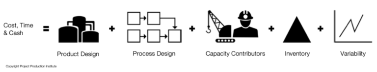
Because project production exists, there are multiple production systems that enable that production to occur. Any of those production systems and processes can be designed and / or optimized taking into account five interconnected levers: 1) the design of the product being produced, e.g., an expansion loop, 2) the design of the work process to build the product, e.g., how the product is fabricated, assembled, transported, installed and commissioned, 3) how the inventory required to build the product will be managed, e.g., how much of what we need where, when, and how often, 4) how the capacity required to build the product will be allocated including contributors such as temporary equipment, tooling, labor and space, and 5) how variability will be reduced and managed, as it cannot be fully eliminated.
In addition to these five levers, Operations Science determines how production systems and associated processes behave, including those of projects, as well as enables the use of production-based analytics. In short, key things to understand are (Operations Science is a much broader body of knowledge):

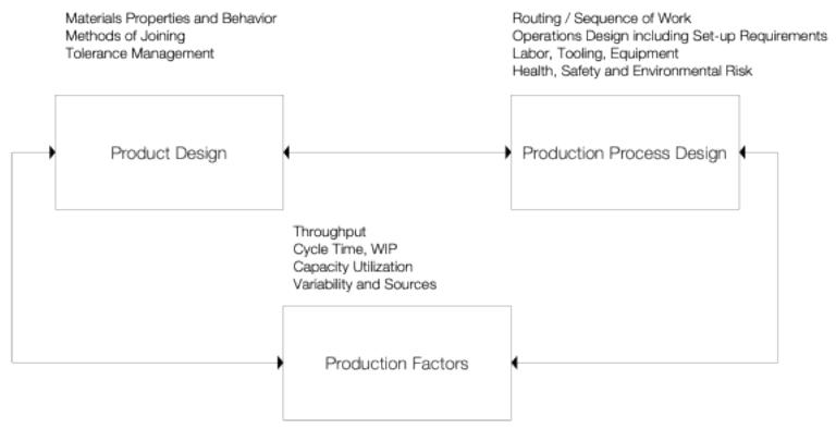
Based on the above frameworks, and in the context of engineering a production process and/or an operation within a production process, there are three key factors at play as depicted in the following schematic: the design of the product, the design of the production process and several production factors.
This paper adopts the Project Production Institute (PPI)’s definitions [6] of Production Engineering and CAPE, which propose the following:
Production Engineering: The application of engineering (electrical, mechanical, structural, etc.), material science, operations science and related knowledge to define, engineer and optimize production processes.
Computer Aided Production Engineering: The application of various computer tools including digital prototypes and 4D visualization, to define, engineer and optimize production processes.
Because of the relationship between product design, process design and the above-mentioned production factors, effective Production Engineering incorporates various fields of engineering and science to effectively design a product and the process to produce it. For project production, these fields often include the involvement of civil engineers, electrical engineers, structural engineers, material specialists, tooling designers / makers, safety engineers, various craft personnel and others as needed. Depending on the product, operations and maintenance personnel may also be involved in a Production Engineering effort (e.g., if we are applying Production Engineering to a foundation or set of foundations in a building, operations and maintenance personnel may not be needed).
Benefits
The effective application of CAPE for project production delivers a combination of performance and developmental benefits as summarized in the following table. In Built to Fail [8], Zabelle expands on these benefits.
| CATEGORY | BENEFITS |
| Performance | Identify and remove health, safety and environmental risks from the operations Compress the time to do the work without putting at risk health, safety, environmental and quality standards, and without necessarily having to add more resources Establish optimal use of resources and the associated opportunities to reduce cost – resources refer to those that contribute to the process capacity (labor, equipment and space) as well as inventory (stocks and work-in-process) Make product design better, so it enhances production performance rather than hampering it Enable ongoing standardization of processes and improvement of work |
| Developmental | Establish the basis for how to enhance capability development including educating and training project teams as well as to develop the workforce Develop bespoke equipment and tools for the work, particularly if the work is repeatable |
Approach
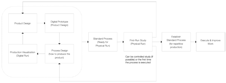
To achieve these benefits, we must establish an approach, a method for how we can tailor the use of CAPE to the project world. The following schematic depicts this graphically combining the use of digital prototyping technology, process modeling [9], digital and physical first-run studies as well as direct insights from doing the work.
During the last three to four decades, the construction industry has incorporated the use of 3D models / 4D visualizations as tools to better delivery projects. However, the use of digital prototyping technology as part of CAPE must include both permanent and temporary components as the intent is to design how work will be done. In the case of maintenance / upgrade projects to existing assets, the existing infrastructure components must also be included. But even today, it is not uncommon to see project teams using ‘engineering’ models that are not ready for production engineering because they are either missing the temporary components (e.g., equipment, tools, visualization of space constraints, etc.) or the models have been structured differently to, for instance, how construction may want to see and chunk work to engineer its execution. Therefore, and unless this has been accounted for during design and engineering, project teams find themselves having to do more work to generate product models that can enable production engineering. The intent is that digital prototypes used for production engineering are as close to a replica of reality as possible throughout the different phases of construction, so the expected work environment is an input to the design of the work and vice versa. Parametric modeling allows for the definition of density of materials, and therefore, enabling the ability to rapidly determine product parameters such as center of gravity, so the implications to process design and product design can be analyzed (e.g., where to locate hoist points and how the hoisting process is set based on that).
CAPE requires we explicitly lay out the process of how we think we can do the work (e.g., fabricate, assemble, load, offload, transport, install, etc.). Creating a process map down to specific details of the operation or production process is essential as multiple iterations are typically expected from that first basis. Production parameters such as rates, durations, manpower, tools and equipment used, space, how work is batched and sequenced, are typically captured. With process models in place, CAPE does not propose linking 3D models with schedules as it is not interested in dates, but rather rates and testing the robustness of production process and product designs including gaining insights before doing the work.
Although the optimal scenario to apply CAPE is during design and engineering so the product and the process are designed concurrently, the fragmented nature of construction does not always allow for this optimal scenario to occur. The application of CAPE during design and engineering represents Concurrent Digital Engineering (CDE), where product and process are concurrently designed. Zabelle et. al. (2019) emphasized that “where conventional design and engineering efforts focus on what will be made or built, production engineering focuses on how parts, assemblies and modules will be built, transported, installed, and commissioned along with how maintenance operations will be accommodated. Production Engineering considers and determines how work will be performed during fabrication, assembly, transportation, installation and commissioning” [7].
When thinking about all the different types of processes and operations that exist in project production from fabrication, assembly, transport, installation and commissioning, CAPE can be perceived as an overwhelming task to be performed for every process and operation. The fact is that CAPE applied to project production provides substantial return on investment in two main scenarios: 1) when used to design and optimize a repetitive production process so a standard process is defined, tested and set for repetitive execution, and 2) when used to design and optimize a one-off production process that is identified as critical and/or complex, in which case there is only one chance to get it right.
It is important to acknowledge that if Production Engineering is pushed later into the project life cycle, the ability to influence the outcome is reduced. In other words, optimal combinations of product and process design identified during early design and engineering are far more plentiful than when a site team attempts to install what engineering has done. But to say that the engineering and construction industry does not engineer project production is probably a mistake, just because project team members make decisions throughout the project lifecycle that one way or another dictate how production is engineered. To say that this happens through a structured approach and that the output is the most optimal one is a different thing.
Many may argue that the engineering and construction industry is too fragmented to adopt CAPE. It is indeed true that the industry is probably one of the most fragmented and disjointed, however, we must look closer at the opportunities in front of us and explore options. The application of CAPE can occur at different stages of project delivery, from engineering through construction and commissioning, recognizing that the value to be unlocked is greater the earlier it is applied. This does not mean, however, the application of CAPE during construction (after engineering is arguably fully completed) is not possible. It is, but the value it can deliver reduces as opportunities to modify product design may no longer be possible, but production for that product design can still be engineered within a smaller design space. In cases where design is complete and the physical completion of the project is underway; CAPE is best utilized in a very targeted manner. Elements of the build which are most at risk of overruns could be a target area.
Computational power opens a new world for those in engineering and construction as we can move from a point-based production process design to a set-based production process design very rapidly, in seconds, not hours, not days, not weeks. Combining the use of this computational power with Operations Science as the technical framework and modeling methods such as Analytical Modeling and Discrete Event Simulation, offers the opportunity to augment the application of CAPE by modeling and simulating the production system that produces the product. In so doing, determine if the design of the overall production system can meet demand or not, and if not, why, identify the bottleneck(s), balance the system, determine optimal values for work-in-process (WIP) levels across the system, implications to cycle time and system throughput if WIP decreases or increases, determine the total and optimal amount of capacity contributors (manpower, tools, equipment, space) needed to meet demand, model the impact of variability levels, the impact of queueing, as well as what control protocols and mechanisms are best suited for the production system. To illustrate, the following section briefly presents an application of modeling and simulation to augment CAPE.
This section presents two examples where CAPE was applied at different stages in the project delivery process. The first example uses CAPE during construction, including fabrication, assembly, transport and installation, with some limitations to influence product design, while the second example describes the use and benefits of CAPE during early design phases to concurrently design product and process.
The development of oil fields includes not only wells, well pads, compression stations, gathering lines, but also pipelines to gather oil and gas to be processed or to transport processed products to markets. In some cases, the fluids are extremely hot causing significant thermal expansion of the pipelines, which must have expansion loops to maintain integrity of the system.
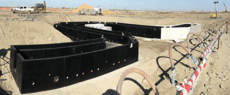
This example includes the execution of 93 expansion loops on an oil field gathering system, which for multiple safety reasons had to be buried underground. In this case, CAPE was applied after loop design and engineering were completed, so the opportunity to concurrently design and engineer the loops and the process to produce the loops was missed. However, this application exposed several product design improvements, which will be discussed later. Loop design included the use of multiple types of precast elements (boxes) that when connected create a physical enclose for the pipe. The following photo illustrates one of these loops and gives a sense of its physical dimensions. The design of each loop is different varying from 10 to 70 meters long, while all loops require a total of 3,300 precast elements (an average of 35 precast boxes per loop). The application of CAPE focused on how to fabricate, assemble, transport and install these 3,300 precast elements including the pipe and its supports.
The fabrication and assembly of the precast boxes was conducted at a dedicated facility adjacent to the oil field, which was purposely built for this scope and included dedicated labor, equipment and transportation resources. The application of CAPE was conducted by the Project Owner with participation from the Contractor doing the work. Jointly, they reduced the production cycle times by 30%, labor cost by USD 5 million, while identifying nine issues related to the design of the loops including the precast boxes as well as close to thirty fabrication and installation improvement opportunities as three First-Run Studies were conducted.
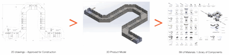
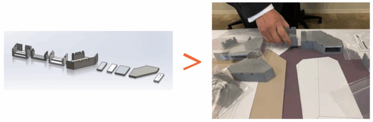
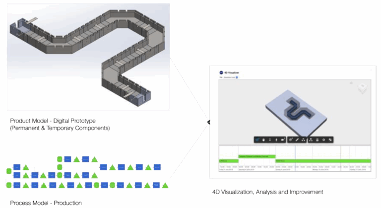
Given the design of a loop and its components was completed before CAPE started and 2D drawings were approved and released for construction, the first step in this effort was to use the 2D drawings to generate 3D digital prototypes of the product design using parametric modeling tools, and in so doing, create a detailed bill of materials and library of components across all loops. Furthermore, the creation of a 3D prototype enabled 3D printing of all boxes for a representative loop, so the project team can also analyze installation operations with a physical model to scale.
The work with the 3D digital prototype enabled the identification of several issues with engineering in the approved for construction drawings. For instance, and just to mention few, lack of proper amount of space to effectively weld the pipe support onto metal plates inside the loop, lack of concrete chamfers to avoid quality issues with concrete borders breaking, blinding concrete width and thickness insufficient to support 3-ton precast pieces, different ground slopes were expected across the 93 expansion loop locations so what are the implications for effective precast site installations, the pipeline entry / exit points required a metal plate bolted to the concrete, then an HDPE sheet and a 200 mm thick insulation, but no details were defined for how these three layers are put together and installed. The analysis of process design, to be introduced next, exposed the need to adjust the structural design of the product (the boxes) to facilitate better fabrication and installation processes by adding additional lifting points as the boxes were flipped and lifted in stages. Those extra lifting points needed to be properly reinforced through structural analysis.
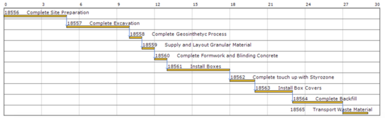
As the team in charge of the works was already doing some planning, the CAPE support team asked to look at how they were planning to do the work, more specifically, if they have developed some process map or anything that may define what the production process is going to be. The response was a Gannt Chart that included only the on-site process, not how precast boxes were going to be fabricated, assembled, delivered and installed. This also proved a point made earlier on this paper that people believe that because a Gantt Chart exists, the production process is engineered.
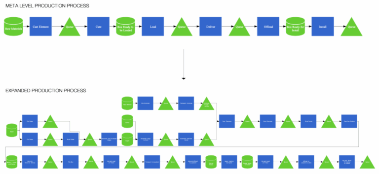
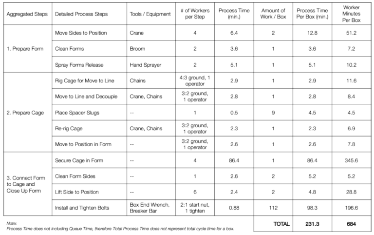
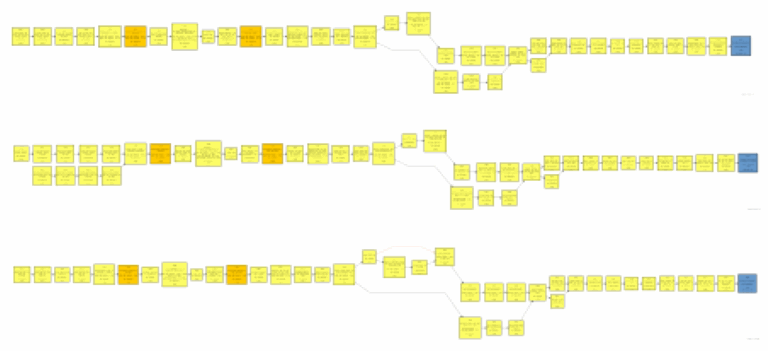
From this point forward, the design of the production process considered first a meta level view followed by expanded and detailed production processes that informed the first-run studies. The process analysis included how to fabricate and assemble the precast boxes, how to apply coating, flip boxes, transport to laydown including load and offload from the truck, deliver to the point of installation and the installation process itself. Specific details such as crew sizes, proper tooling, equipment, hoisting procedures, process times, etc., were defined during the studies as shown next.
With access to a construction 3D model (temporary and permanent components) and the process, the application of CAPE for this effort included the use of 4D visualization, analysis and improvement focusing on HOW to do the work. Multiple 4D visualization analyses were conducted to test work sequence, safety risks, use of space, ergonomics, use of resources such as cranes, trucks, etc. and determine in real time either negative or positive implications to cycle times, all prior to physically doing the work. The output of virtual studies are standard processes that become the input for the first-run studies.
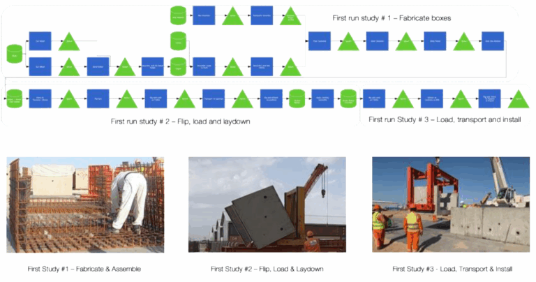
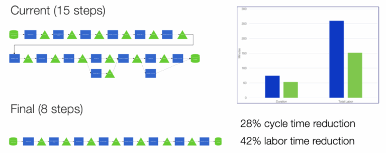
Moving from virtual to first-run, physical studies enabled further testing the robustness of the standard production processes and identifying any new improvements. A key output of first-run studies is an improved standard processes for fabrication, assembly, load, offload, transport, and install. To illustrate, this application of CAPE included three first-run studies as shown next. It is not possible to include all outputs of these three studies herein, however, the table below and the subsequent section provide the type of data captured as well as what was unlocked through this analysis to further improve the production processes including cycle time reductions in the order of 20-50% and reducing labor capacity in the order of 40%.
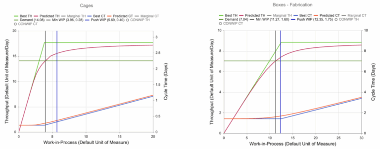
Using Analytical Modeling and Discrete Event Simulation, production system models were created to understand how the overall system behaves when responding to the desired demand (desired throughput), including, for instance, the identification of bottlenecks (resource with highest capacity utilization) as well as optimal values for work-in-process as targets for production control. The 93 loops needed to be completed in about 27 months, which means the production system must respond to an average demand rate of 3.44 loops / month or 0.86 loops / week. The next Figure represents the model of the end-to-end production system including fabrication, assembly, transportation and installation of precast boxes.

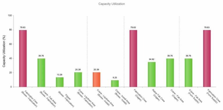
With several inputs to the model including, but not limited to, the demand, process times, transfer and process batches, variability levels, types of resources, amounts and allocations to the operations in the process, the Analytical Model determined, for instance, that the optimal number of rebar cages to be fabricated and assembled at any given time should be six, no more, no less. Allowing more than 06 rebar cages in the system will rapidly increase the cycle time to make them while not gaining much more throughput. If the number of cages is lower than six, it will starve the downstream portion of the system. Similarly, for the portion of the production system that makes the precast boxes, the optimal number of boxes in WIP should be thirteen. Furthermore, the resource with the highest capacity utilization is the boxes fabrication crew with close to 80% utilization (refer to Figure 12). Other resources had some extra capacity to absorb variability.
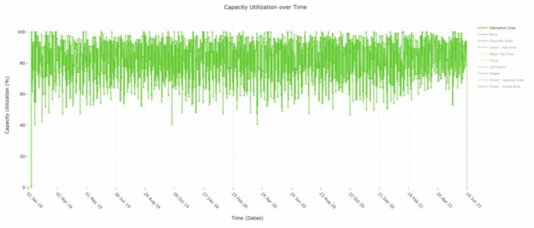
The execution of first-run studies offers an opportunity to update the production system model to validate the system behavior and check if any adjustments to the production system design are needed. During execution, actual production data can feed the model enabling a Digital Twin of the Production System [9].
As CAPE is about engineering production processes and operations, the type of leanings and improvements are not only associated with cycle time reduction, labor optimization, etc., but also the intricate details of what to adjust to do the work more efficiently – in other words, the how to do it better. Therefore, this section provides a summary of the most important learnings and improvements (in no order of priority or relevance) made to the overall production process through CAPE.
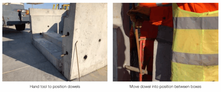
14. The engineering of the boxes required the use of four dowels on the side of each box, in principle, to serve as an alignment mechanism between boxes. However, the tolerance between a hole and a dowel was larger than the crane’s placement accuracy for a box, so the use of dowels provided no help with alignment. Also, engineering required holes of 500 mm in length, but at the time of fabrication, they were observed to be substantially shallower than designed. Eliminating the holes and use of the dowels removed not only a source of errors and variability during operations, but also safety hazards of potentially crushing hands if trying to insert dowels by hand while moving the boxes together.
15. Other sources of variability in the overall production process included the different designs of the precast boxes, which leads to variation in production rates and raw process times, as well as how work is batched throughout the process including work release rates from operation to operation.
This is the case of an existing industrial facility with several years in operation that identified the need to replace power and communication cables having to perform + 2,000 cable cutovers and splices across several locations in the operating facility. Although the project included several other scopes, the project owner looked at the application of CAPE to define, design, and standardize the cable cutover processes to the extent possible, and therefore, minimize any disruptions to existing business operations. Compared to the previous application example (expansion loops), CAPE was applied during the pre-FEED (Front-End Engineering Development) Phase as the means to conduct concurrent analysis and development of process and product design. There were many challenges to this project, but two stood out: 1) due to the age of existing facility, accurate as-builts were not available, and 2) as the process was intended to be completed over several weeks, most of the cable in the racks were to be kept energized.
Using CAPE, the team identified, designed and agreed on sixteen different types of cutover process design configurations for power and control cables including establishing cycle time targets, all of which were neither existing processes nor approved designs. Based on the volume of work and complexity, this analysis also concluded the need to use five independent crews working concurrently at different locations. Previously unidentified constraints such as logistics of cable installation around existing pipe racks as well as limitations that impact the routing of new cable to its ultimate splicing point were exposed and addressed. Numerous safety concerns were identified in advanced including, but not limited to, potential risks of splicing on existing cable tray over top of live cables, manipulating live cables at elevation and crew members performing their tasks in high fall-risk environments; and eventually exploring potential solutions to these risks such as changing splicing locations to new cable trays with less live cables and changing splicing locations to require less overall movement of existing cables.
Given the large volume of cutovers and potential variations, the strategy for process design was to identify types of process configurations based on known site conditions as well as technical requirements to be fulfilled. Based on this, 08 different types of process configurations for power cables, plus additional 08 configurations for control cables, which included variants with power cables done inside of the substation, outside of the substation, and cable test fails at any one of three required test points. Similarly, in the case of control cables, the differences in these processes related to whether the cables were connected in a junction box or directly on the rack as well as differences in test failure points.
For each of these configurations, the starting point to develop a standard sequence of work (process design) was to list all known steps required for each type of splice while making some educated assumptions based on past experiences to define a high-level sequence.
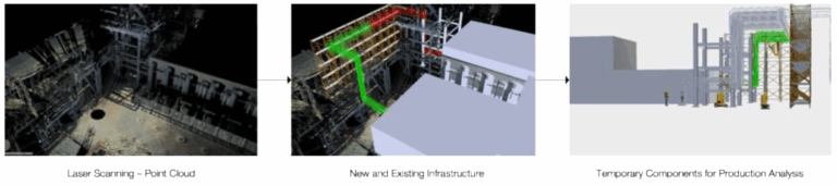
Being an existing facility, CAPE needed to address existing infrastructure elements, so laser scanning was used to digitally capture these elements and then translate point clouds into 3D models. With a 3D environment created, new permanent components (e.g., cable trays, supports, cables, etc.) and temporary elements (e.g., scaffold, manlifts) were added for the purpose of analyzing how to do the work under specific field conditions.
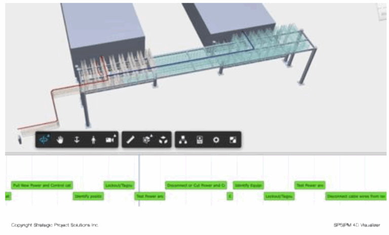
With the addition of temporary elements, the team was able to create 4D visualizations that combined the 3D product model and the latest process design. The intent was to test if the designs of the process and product are robust or required adjustments. The 4D visualization enabled individual components of the 3D product model to be linked to the operations as per the process design. As with any design process, iterations were expected resulting in modifications to the 3D product model, modifications to the standard process, or both. As one critical aspect of this effort was to make decisions on cable splice points, color-coded depictions of the cable were added to the 3D product models. In the figure below, the cables are color-coded, and the model is integrated with the standard process represented in the bottom section with green bars. As those involved in the analysis advance through the process by moving the vertical bar through the timeline, the team visualized the progression of old and new cables to the splice points.
CAPE provided extreme value to influence the FEED process by identifying four possible Basis of Designs for cable cutovers. Another value CAPE provided was alignment on the complexity of the process and the direction the construction process should take. Initially, the team wasn’t aligned regarding sequence or duration, but the effort ended with agreement on what the high-level cutover process should be. Because it was early in the project delivery process, there was still little definition on the access limitations for the actual splices mainly due to extreme congestion that was not able to be modelled given the current lack of as-builts or engineering.
This paper has provided a framework for the application of Computer-Aided Production Engineering as a Project Production Management methodology to define, engineer, test and standardize project production processes and operations. Using applications examples, this paper not only demonstrated the technical feasibility of applying CAPE to project production at different project stages, but also the significant opportunities that exist in construction to compress cycle times by 20-50% (or more) without adding more resources, reduce labor capacity needs by 40%, while identifying and removing production-based and safety risks. This contributes to addressing the lack of access to the necessary manpower across the industry.
The application of CAPE, including the use of techniques such as Design for Manufacturing & Assembly (DfMA) and enabling technologies, ensures robust engineering and standardization of production processes, which then become the basis for control and improvement as work is executed. There is no doubt that a significant opportunity exists to perform Production Engineering ‘during Engineering’ so design of the production process and the product are performed concurrently, unlocking additional value trapped.
This paper has also illustrated that the power resides in the combination of three key elements: 1) the involvement of individuals that know about production (how to build, not how to buy), 2) the use of a systematic, structured and scientific approach that drives engineering, standardization and optimization versus just asking people to collaborate, 3) the concurrency of product and process design, and 4) the application and use of leading edge computational technology for product / process design and visualization, as well as the opportunity to augment CAPE with Analytical Modeling and Discrete Event Simulation to model and simulate the behavior of the production system and determine what needs to be done to optimize it.